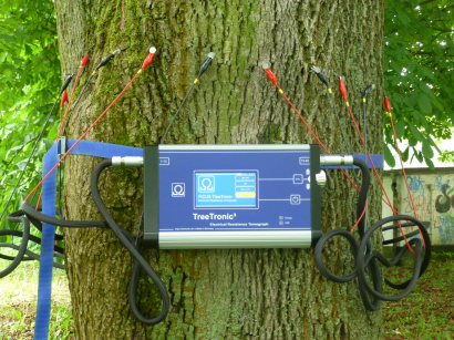
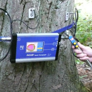
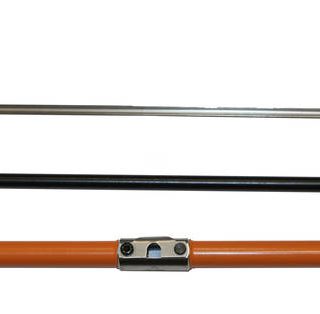
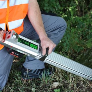
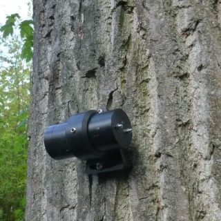
The electric Resistance Tomograph PiCUS : TreeTronic is used in conjunction with the PiCUS Sonic Tomograph for tree risk assessment in order to get detailed information about the thickness of the residual walls and type of stage of a defect such as decay. The TreeTronic tomograms show in particular the early stages of decay and support in analyzing sonic tomograms. The combined application of the PiCUS Sonic Tomograph and the Treetronic is the most advanced imaging technology for tree inspections.
The PiCUS : TreeTronic is measuring the electric resistance of the wood of a tree. The electric resistance of the wood is greatly influenced by the moisture content. Most fungi or decay are increasing the moisture content and therefore decreasing the electric resistance. Chemical composition of the wood and the cell structure also affect the electric resistance of the wood.
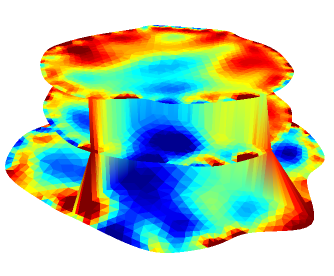
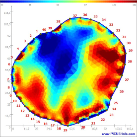
While a TreeTronic scan the device is step by step applying electric voltages of up to 100 Volt to all the measuring points that are placed around the circumference of the measuring level and that is causing an electric field inside the trunk. Basically, the TreeTronic is measuring how the inhomogenous wood is distorting this elctric field. After all measurements have been taken a complex software is calculating the apparent electric resistance of the wood in – strictly speaking around – the measuring level. The outcome of the calculation is the coloured map: the so called Electric Resistance Tomogramm – ERT.
The ERT is used mostly in conjunction with the sonic tomography (SoT) scans and enables the operator to analyse type of defect (decay – cavity) and size of the residual walls in trees with defects more precisely. ERT Tomograms are very sensitive to detect early stages of decay. In contrast to sonic tomography the accuracy of TreeTronic scans do suffer less from cracks in the tree trunks.
How to read ERT data
The main aspect of interpreting ERTs is the distribution of high and low conductive areas. You are looking to see where high resistance is and where low resistance is. This information needs to be compared with the normal resistance distribution in sound trees of this particular species.
The actual value of the resistance given in a tomogram is less important and less accurate, due to the ambiguity of the measuring method.
So far we have identified three types of typical resistivity distributions in trees which we simply call ERT Type 1, 2 and 3 (from left to right).
ERT Type 1
Low resistance (high conductivity = blue colours) on the outside and high resistance (lower conductivity = red colours) towards the inside of the tree. The ERT on the left in the above example shows the normal resistance distribution of a sound beech tree. The heartwood of beech trees is less conductive (higher resistance) than the edge of the tree. The blue the ring on the outside shows the bark/sapwood for water transportation.
Most of the European tree species belong to this group:
Acer, Asculus, Betula, Castanea sativa, Fagus, Fraxinus, Larix, Pine, Picea, Populus, Salix, Sorbus, Tilia, Ulmus and others.
Species like Asculus or Populus often develop internal wet wood even when they are young. The wet wood changes the resistivity of the heartwood. Early stages of the wet wood do not pose a risk for the stem breaking stability.
ERT Type 2
High resistance (low conductivity – red colours) on the outside and low resistance (high conductivity – blue colours) towards the inside of the tree. The example above (in the middle) is an ERT of a sound sequoia giganteum tree shows low resistance in the centre – blue colours). The bark/sap-wood has higher resistivity – red colours than the heartwood. That does not (!) mean the sapwood is dry! The absolute values of the sapwood indicate that the wood is conductive – because of the moisture content, it is not dry – but it is less resistance is higher than the resistance of the heartwood.
Examples are: Sequoiadendron giganteum, Casuarina, Tectona Grandis (Teak)
ERT Type 3
Type 3 ERTs show a ring – like R distribution. In the example above on the right the ERT was taken on Quercus robur.
In the ERT the blue ring – low resistance- on the outside represents bark/sapwood. The blue low resistance centre of that Quercus robur is caused by high concentration of several ions (Refer to Bieker/Rust Electric resistivity tomography shows radial variation of electrolytes in quercus robur. Canadian Journal of Forest Research 40:1189–1193). These tomograms are typical for soundQuercus robur trees.

